(608) 346-2392 info@innalytical.com

Analysis & Simulation

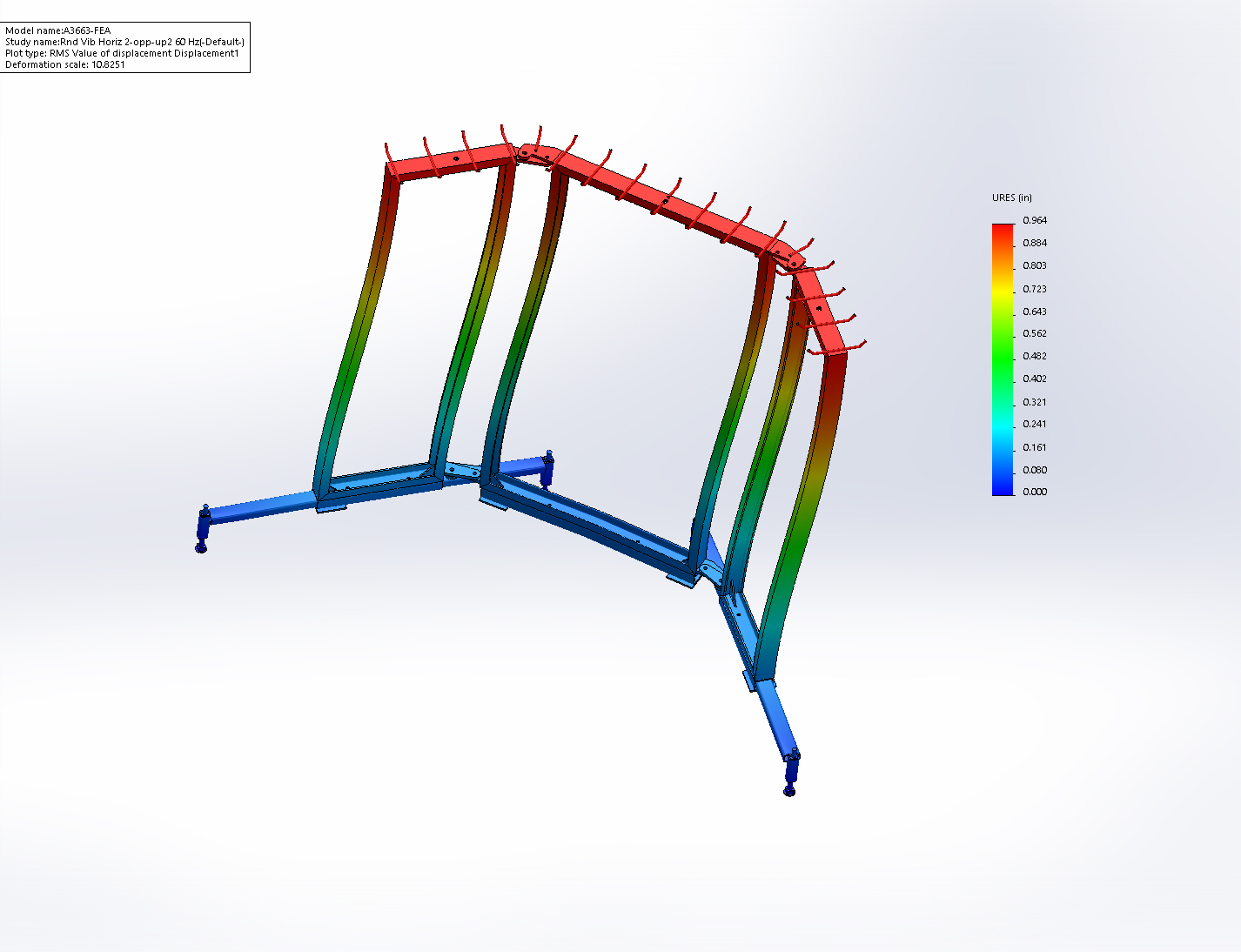
Innalytical Solutions uses various tools to simulate and/or analyze mechanisms of all types.  We use Finite Element Analysis (FEA) to conduct structural analysis of mechanical components and assemblies.  We can also provide graphical simulations (animations) of mechanical assemblies.

Our founder has been using FEA for over 35 years.  Please review our collection of sample projects below.

Super Bowl Stage FEA Results

Client Comments

We have had the pleasure of working with Paul for many years and he is very thorough and professional. Paul is a highly skilled engineer and completely hands on person. I would highly recommend Paul for anything in the scope of engineering and problem-solving.

Don Miller

JAC Manufacturing inc.

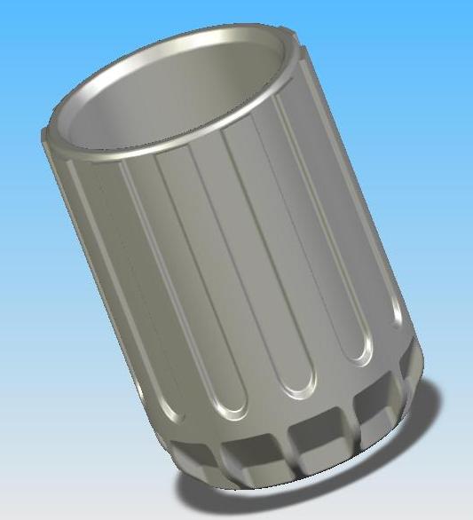
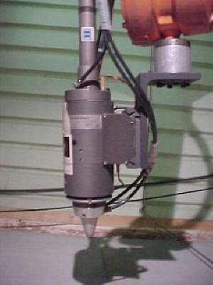
Sample Analysis / Simulation Projects

Shield Support Analysis

A company that provides radiation shielding and contamination control products for commercial nuclear power, nuclear medicine and industrial radiography lacked FEA analysis capabilities.

Innalytical Solutions provides FEA analysis for this client when failure of their products could be catastrophic.  These analysis range from very simple static analysis to studying the reaction of structures to the random vibrations of an earthquake. 

Oil Valve

Shutoff Valve Analysis / Simulation

The challenge was to ensure that a shutoff valve, operating 5,000 feet below sea level, had adequate clearance to function in spite of the great water pressure applied to the device.

Innalytical Solutions completed the a finite element analysis of the valve design to verify the deflection caused by the water pressure did not affect its operation. 

Complete Roof & Rack Assembly - 20 G Side Collision Deflection

Roof Rack Analysis

Our customer was faced with a significant hurdle. Their sensor system was not allowed in certain European countries because of concerns for its safety. The sensor, used widely in the United States, was mounted to the roof of a station wagon and driven down streets and highways while data was being collected. The concern was that the weight of the sensor exceeded the rated roof rack capacity of the automobile manufacturer.

The solution was to provide a thorough Finite Element Analysis of the sensor and its support structure mounted to the automobile roof. The combined assembly was subjected to dynamic loads of up to 60 Gs to determine the stresses placed upon the individual components.

Super Bowl Television Stage

We were proud to assist our customer, Northern Lights Productions, in the design and analysis of a television set for Fox Sports’ coverage of Super Bowl XLV. The set was designed using our customer’s ModTruss system and configured to provide a cantilevered roof that provided an unobstructed view of Cowboys Stadium.  The roof structure also provided support for television lights.
Upender Table

Upender Table

The challenge was to design a table that tips a large components from vertical to horizontal (upender) with enough strength to support the loads.

The solution was created using SolidWorks to design a heavy duty tilt mechanism and then analyzing the stresses using the SolidWorks simulation (finite element analysis) software.

Hydraulic Valve Test Stand

Hydraulic Valve Test Stand

The challenge was to test a wide variety of hydraulic valve packs in a single test stand.

The solution was test stand with modular fixtures that adapted the different valve packs to the test stand.

Cycle Time Simulation

The challenge was to create an estimate of the time required to complete a programmed cutting cycle on a commercial finishing system. The system consisted of a cutting head mounted on a two axis gantry. The path was created using a graphical program and exported as an HPGL file. The primary concerns were achieving an
error of less than 10% and ease of use.

The solution was to create an Excel spreadsheet to complete the calculations and macros to automate the process. The path data is created by importing the HPGL file and converting each line into the appropriate motion. (Arcs were converted into a series of small linear moves.) The spreadsheet then calculates the time required for each move and generates a total cutting time.

Cycle Time Simulation

The challenge was to analyze various design alternatives for a sophisticated assembly system.

The solution was to create a SolidWorks animation where each step of the assembly process could be simulated and optimized.

Collet Design

The challenge was to design a replacement collet for a two piece retractable rod that would eliminate the rattling created when the two tubes contacted each other.  The concern was applying adequate pressure on the thin tube while keeping the stress on the nylon collet at a safe level. The solution was created using SolidWorks to design an attractive collet and then analyzing the stresses using the SolidWorks finite element analysis software module.  Finally a rapid prototype part was created...

Laser Pierce

The challenge, presented by a large supplier of automobile frame assemblies, was to gain a understanding of what combination of 13 separate parameters created the optimum laser pierced hold in steel. These holes were required for mounting holes and passages in hydro-formed frame rails. Because of the nature of the hydro-forming process these holes had to be added after the rails for formed.

The solution was to create a Design of Experiments matrix utilizing an Excel spreadsheet that allowed the optimum settings to be determined with only a few dozen samples. The result was a huge savings of both time and money as the samples were taken more quickly and the project was completed much faster.

What is FEA?

According to Wikipedia, the finite element method (FEM) is a numerical method for solving engineering problems.  It is also referred to as finite element analysis (FEA).  The analytical solution of these problems generally require the solution to boundary value problems for partial differential equations. The FEM formulation of the problem results in a system of algebraic equations. The method yields approximate values of the unknowns at discrete number of points over the domain.

To solve the problem, it subdivides a large problem into smaller, simpler parts that are called finite elements. The simple equations that model these finite elements are then assembled into a larger system of equations that models the entire problem. FEM then uses variational methods from the calculus of variations to approximate a solution by minimizing an associated error function.

The SimiScale website has a more complete explanation that is worthwhile reading.